


Groove and outside-face guides work differently
A standard fin-style guide normally needs a compatible groove in the bottom edge. A U-channel arrangement guides the outer faces instead. Roller designs also vary: some engage a groove, while others contact a face. Read the drawing for the exact model.
Do not cut a groove in glass, metal, a thin skin or a finished panel unless the door manufacturer specifically approves that preparation. A guide described as adjustable still has limits. Confirm its stated range against the actual panel thickness.
Compare mounting and contact together
| Arrangement | Useful when | Check carefully |
|---|---|---|
| Floor-mounted groove guide | The panel has the correct groove and the floor is suitable for fastening. | Groove dimensions, guide engagement and the flooring requirements. |
| Floor-mounted U-channel | The guide can contact the outside faces of a compatible panel. | Panel thickness, adjustment range and contact clearance. |
| Wall-mounted standard guide | A suitable wall or baseboard location provides the specified support. | Projection, trim depth and whether the guide enters a groove. |
| Roller guide | The selected roller layout suits the panel and finish. | Where the roller contacts the door and which surfaces need anchors. |
A product name is not an installation drawing. In particular, do not assume every guide described as wall-mounted avoids all floor fasteners. Check the exact baseplate and mounting instructions.
Two Rustica guides to compare
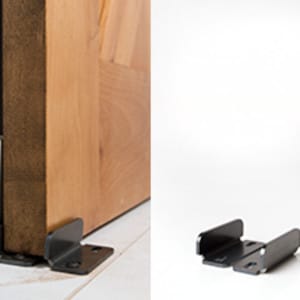

These are specific products, not a complete list of possible guide systems. The included screws do not automatically suit every tile, masonry, wood or other substrate. Have the installer confirm the required fasteners and what lies behind the mounting surface.
Measure the panel and its path
- Panel thickness at the point where the guide will contact it.
- Groove width and depth, if a groove is part of the design.
- Distance from the wall to the moving panel, including trim and baseboards.
- Floor clearance along the entire travel path.
- The proposed guide location with the door fully open and fully closed.
The guide should remain engaged throughout normal travel. Keep it out of the clear passage as required by the layout. Do not place it by estimating halfway across the opening; stops, overlap and the panel’s parking position affect the correct location.
A guide does not replace the other hardware
The guide controls side movement. Track stops limit travel along the rail, and anti-jump devices limit lift at the rollers. Review the barn door hardware parts guide if you are assembling a parts list.
If the door binds, inspect the cause before widening the guide or removing a required part. A track that is out of level, an uneven floor, a warped panel or the wrong guide setting can produce different symptoms.
Follow the selected guide’s installation instructions
Use Rustica’s hardware installation instructions for the exact model. The barn door floor guide installation guide explains the general sequence. Neither replaces the dimensions supplied with the hardware.
For a new installation, choose the guide together with the barn door hardware system. For a replacement, identify the existing hardware and panel preparation before ordering a part that merely looks similar.
Planning a client project?
Planning sliding doors for a client’s tile or wood floors? Confirm guide mounting before finalizing the quote. Rustica’s contractor discount program explains professional eligibility and how to apply.