1.800.891.8312
Free Shipping Details
Most orders over $500 qualify. Free shipping applies to Barn Door Hardware, Barn Doors, and Pocket Doors over $500.
Note: Front doors, interior doors, shower doors, any oversized door (wider than 3ft and taller than 7ft) and any special order doors have shipping costs calculated at checkout. Some barn door hardware track lengths do not qualify for free shipping.


Triple Bypass System Assembly Instructions
Triple Bypass System Assembly Instructions & Video
Triple Bypass System Recommended Tools
- Drill with a 1/4” Drill Bit and Phillips Bit
- 7/16” Combination Wrench
- Socket Wrench with 9/16” and 7/16” Sockets
- Level
- Tape Measure
- Pencil
Triple Bypass System Parts
- Bypass Bracket
- Lag Screw
- Lag Bolt
- 3" Wood Screw
- 1" Phillips Screw
- Washer
- Come-Along Door Guide (optional)
- Door Guide
- End Plate
- Hard Stop & Rubber Bumper
- Track
Triple Bypass System Assembly Instructions
First Things FirstCheck to see if the floor below the track area is level. If the floor rises more than 1/2” the door may rub or not slide open completely. If the floor is not level, measure from the highest point of the floor surface to the recommended track placement and adjust track placement accordingly.
Ensure the track will be installed onto wall studs. If wall studs are not lining up with the installation a header will be required to provide the necessary strength and stability for the track and door.
Step 1: To determine where the track should be installed, first measure the height of the door, then add 2-1/8” to the door length. 1/2” will be for the clearance between the bottom edge of the door and the floor. 1-5/8” will be from the top edge of the door to the center of the track. (Figure 1).

Step 2: Using a level and a pencil, make a line above the doorway the same length as the track.
Header Installation
Note: The header should be 6” tall and 4” longer than the track.
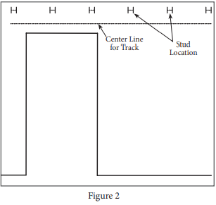
Step 3: Using a stud finder, locate the studs along the area the header will be installed. Mark stud locations with a pencil (Figure 2).
Step 4: Lay the header on a flat clean surface. Using a measuring tape, measure 2” from the bottom of the header. Draw a line the length of the header with a pencil (Figure 3).

Step 5: Lay the track (K.) on top of the header, centering it with the line drawn on the header. Ensure the track is 2” from either end of the header. Using a pencil, mark the hole positions in the track onto the header (Figure 4). Set the track aside.

Step 6: Mark the center of the stud onto the header. Mark 1” from the top edge and 1” above the bottom edge (Figure 5).

Step 6a: Center the bypass bracket (A.) on the first vertical pencil line with the bottom of the bracket edge touching the bottom horizontal pencil line. Mark the center of each of the four holes in the bracket back. Repeat for remaining brackets.

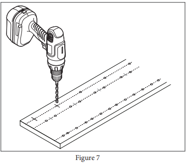
Step 7: Drill out the marked holes using a drill with a 1/4” drill bit (Figure 7).
Step 8: Align the line on the wall with the line made on the header in step 4. Ensure pilot holes align with wall studs (Figure 8).
Step 9: Install header using 3” wood screws (D.) (Figure 8).

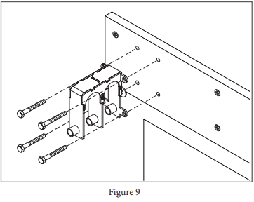
Step 10: Install brackets (A.) with a socket wrench using lag screws (B.) (Figure 9).
Step 11: Begining with the track closest to the wall, install each track completely before moving on to the next track (Figure 10).

Step 11a: For brackets between end brackets, install each track using a socket wrench and one lag screw (B.) (Figure 10a).

Step 11b: For brackets end brackets, install each track using a socket wrench and one lag screw (B.) (Figure 10b).

Step 12: Stretch rubber bumper (J.) over hard stops. Repeat for the hard stops on the other end of the track (Figure 11).

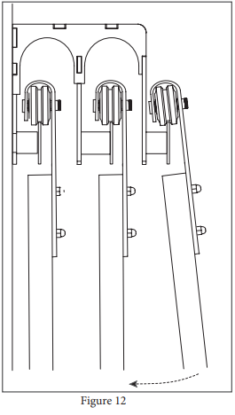
Step 13: Hang the doors (Figure 12).
Panel/Door Guide Installation
Step 14: With the panel or door in the closed position, ensure the panel or door is hanging straight using a bubble level.
Step 15: Position the Door Guide part way into the groove in the bottom of the panel or door (Figure 13).

Suggestion: Use double stick tape on the bottom of the door guide to hold the guide in place.
Step 16: Install the Door Guide using a 1” phillips screw (provided) and a drill with a phillips bit.
Step 17: Slide the panel or door toward the open position until the other side of the Door Guide is exposed.
Step 18: Install the second 1” phillips screw (provided) using a drill with a phillips bit (Figure 14).

Come-Along Panel/Door Guide Installation
Step 19: Slide both panels or doors toward the open position, sliding the front panel or door past the back for access to the back panel or door lower edge (Figure 15).
Step 20: Mark a line 1-1/6” from the edge of the panel or door (Figure 15).
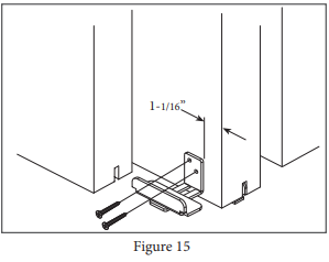
Suggestion: Use double stick tape on the back of the Come-Along Door Guide to hold the guide in place.
Step 21: Align the Come-Along edge to the pencil line and slightly above the panel or door’s bottom edge to prevent scraping on the floor. Ensure that the groove from the front panel or door can pass over the Come-Along.
Step 22: Install the Come-Along with two phillips screws (provided) using a drill with a phillips bit.
Panel/Door End Plate Installation
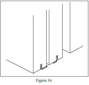
Step 23: Position panels or doors over door guides as shown (Figure 16).
Step 24: Position the End Plate on the bottom edge of the panel or door, aligning the plate with the side and bottom edges of the door (Figure 17).

Suggestion: Use double stick tape on the back of the End Plate to hold the plate in place.
Step 25: Install plate with two flat head phillips screws (provided) and a drill with a phillips bit (Figure 18).

Step 26: Repeat steps 23 through 25 for the other end of the panel or door.


PRODUCTS
FEATURES
COMPANY
BUSINESS