1.800.891.8312
Free Shipping Details
Most orders over $500 qualify. Free shipping applies to Barn Door Hardware, Barn Doors, and Pocket Doors over $500.
Note: Front doors, interior doors, shower doors, any oversized door (wider than 3ft and taller than 7ft) and any special order doors have shipping costs calculated at checkout. Some barn door hardware track lengths do not qualify for free shipping.


Low Clearance System Assembly Instructions
Low Clearance System Assembly Instructions & Video
Low Clearance System Recommended Tools
- Drill with 1/8”a 1/4” and 3/8" Drill Bits, and Phillips Bit
- Socket Wrench with 9/16” Sockets
- 7/32" Allen Wrench
- Level
- Tape Measure
- Pencil
System Specifications
Low Clearance System Parts
Use Teamwork. We recommend two people for this build.
Low Clearance System Assembly Instructions
NOTE: Doors using Floor Mount Door Guides will have a groove on the bottom. Ensure this groove is on the opposite end of the Door Hanger Installation.
 Hanger Installation
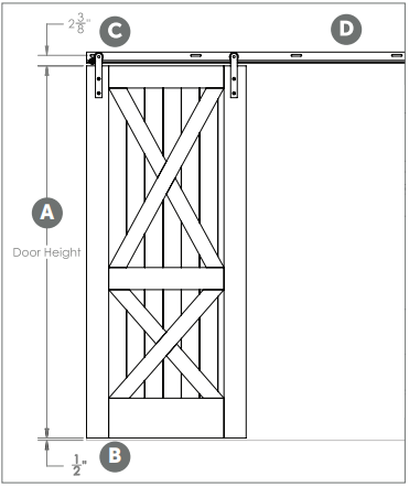
A: Lay the door face up on a smooth, level surface.
B: Place the hanger on the door

C: Adjust the placement of the hanger for a 2-3/4” gap between the top of the door and the top hole in the hanger.
D: The side of the hanger should rest around 2” from the edge of the door.
E: Mark the center of each installation hole with a pencil.

Repeat steps C-E for the opposite end of the door. Set the hangers aside.
A: Drill two pilot holes all the way through the door for each hanger using a drill with an 1/8” drill door for each hanger using a drill with an 1/8” drill bit.

B: Turn the door over. Using a 1-1/8” Forstner bit*, drill a 7/16” deep hole into each pilot hole.
*A 1-1/8” Spade bit may be used in pace of a Forstner bit.

C: Turn the door over, returning it to the face-up position. Drill all the way through the pilot holes using a drill with a 3/8” drill bit.

D: Install the hangers to the front of the door using lag bolts, washers, and acorn nuts (provided).
 First Things First
Check to see if the floor below the track area is level. If the floor rises more than 1/2” the door may rub or not slide open completely. If the floor is not level, measure from the highest point of the floor surface to the recommended track placement and adjust track placement accordingly.
Ensure the track will be installed onto wall studs. If wall studs are not lining up with the installation a header will be required to provide the necessary strength and stability for the track and door.
A: To determine where the track should be installed, first measure the height of the door, then add 2-7/8” to the door height.
B: 1/2” of this total will be for the clearance between the bottom edge of the door and the floor.
C: 2-3/8"” will be from the top edge of the door to the center of the hole.
D: Using a level and a pencil, make a line above the doorway the same length as the track.
E: Hold the track up to where the pencil line is visible through the holes in the track.

Suggestion: Use pieces of double stick tape on the back of the track to help hold the track in place while completing steps D and E.
F: Mark an intersecting line inside each slotted hole wherever they work best for your wall (i.e. stud locations).
Take the track down, remove double stick tape (if used) and set the track aside.
A: Drill out the marked holes using a drill with a 1/4” drill bit.

B: Attach one end of the track to the wall with C: a lag screw and D: one washer (provided) using a socket wrench with 9/16” socket. Do not tighten.

E: Install remaining lag screws (provided) using a 9/16” socket wrench. Tighten all lag screws.

A: Hang the door.

Door Guide Installation
B: With the door in the closed position, ensure the door is hanging straight using a bubble level.
C: Position the Door Guide part way into the groove in the bottom of the door.

Suggestion: Use double stick tape on the bottom of the door guide to hold the guide in place.
D: Install the Door Guide using a Phillips screw (provided) and a drill with a phillips bit.
E: Slide the door toward the open position until the other side of the Door Guide is exposed.
F: Install the second Phillips screw (provided) using a drill with a phillips bit.

Adjustable Stop Installation
A: Place the adjustable stop on your track.

B: Position along the length of your track to stop door at the desired location. Tighten bolt with a 9/16” wrench/socket.


Hitching Post
Event Venue
1520 N Main Street
Springville UT 84663

PRODUCTS
FEATURES
COMPANY
BUSINESS