


1. Check how much of the opening stays clear
Measure the finished opening and sketch the doors closed, partly open and fully stacked. Include side coverage and the required overlap where the leaves pass. If the stack remains within the opening, it continues to cover part of it; bypass movement does not make the whole opening disappear.
Mark the storage, drawers and furniture behind the doors. A closet drawer bank may need a different panel arrangement from open shelving. Where extra wall parking is available, a longer compatible track arrangement can change the usable access.
The sliding closet door guide includes an overlap calculation. For doors that meet at the center and park on opposite walls in the same plane, use the bi-parting installation guide instead.
Compare bypass doors and bypass hardware before planning the installation. For offset double-track options, see double-track bypass hardware. Match the exact kit to its manual.
A simple bypass-door width example
For two equal-width doors, add the finished opening width, the coverage at both sides and the overlap between the doors. Divide that total by two. This gives a starting panel width to check against the hardware instructions.
EXAMPLE ONLY
(60 + 1 + 1 + 2) ÷ 2 = 32 inches
A 60-inch opening, 1 inch of coverage on each side and 2 inches of overlap would need two 32-inch doors.
Those allowances are examples, not Rustica installation requirements. Door thickness, handles, guides and stops can change the layout. Track length and panel stacking determine how much of the opening stays clear.
| Measurement | What to include |
|---|---|
| Finished opening | Width and height after trim and flooring are complete. |
| Panel overlap | The overlap required by the selected system at the center and sides. |
| Wall projection | Trim, rear pull, panel thickness and the space between the doors. |
| Headroom | The space needed above the door for track, hangers and installation. |
| Usable access | The clear opening with the doors stacked, including access to drawers. |
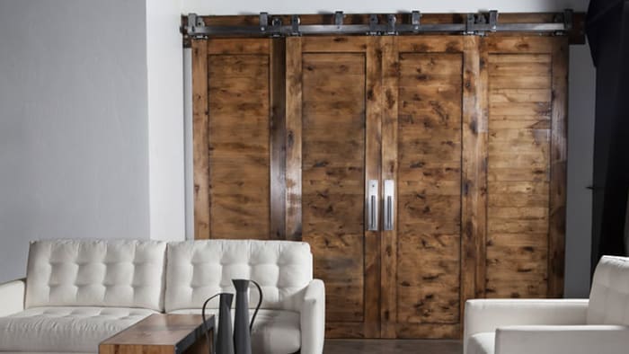
2. Match the manual to the supplied hardware
| System | What distinguishes it | Manual |
|---|---|---|
| Light Duty Bypass | Separate front and rear tracks with bypass brackets. | Light Duty Bypass instructions |
| Adjustable Heavy Duty Bypass | Bracket adjustment changes the spacing between the door paths. | Adjustable Heavy Duty instructions |
| Grapple Single Track Bypass | Matched straight and angled hangers create the offset paths on one flat track. | Grapple instructions |
Match the manual revision, supplied components and order. Count the hangers, brackets, spacers, fasteners, stops, guides and retention parts. Add the instructions for any soft-close units or track splices. The terms “light duty” and “heavy duty” do not replace the actual capacity specification for your door weights.
3. Lay out height, projection and support together
Check the floor across the entire door travel and establish the high point. Use the selected hanger and track dimensions to calculate a level mounting line and the required bottom clearance. Also measure the overhead space needed to assemble and retain the hangers.
Draw a side section showing the wall, trim, rear leaf, front leaf and handles. Include thick overlays, bolt heads and the rear pull. The front door must pass without striking the rear door’s hardware, and both grips must remain reachable.
Provide the structural attachment required for the completed pair. Locate suitable framing or specify a support header anchored into framing. A board fixed with generic trim screws, or drywall anchors chosen by convenience, is not a substitute for the system’s required attachment.
4. Mark and install the mounting components
Use the actual bracket and track-hole pattern to transfer the mounting locations. Check the relationship between the track centerline and the bracket holes; placing a header an arbitrary two inches above the opening does not establish that geometry.
Drill the pilot holes specified for the fastener and substrate, then install the header or mounting structure and brackets in the manual’s order. Keep the reference lines level and the bracket positions aligned. Resolve framing or utility conflicts before committing to the holes.
On an adjustable bracket system, use the designed adjustment range and locking fasteners. Do not extend the projection with an improvised stack of washers or substitute a spacer from an unrelated kit.
5. Prepare the leaves before obstructing access
Identify which leaf runs nearest the wall. Prepare the hangers, handles and guide grooves while the doors are supported on a protected surface. Follow the correct template for each hanger; a single-track bypass pair may use different hanger shapes on the two leaves.
Confirm that the door construction accepts the preparation. Use the prescribed fasteners and countersinks so rear projections do not interfere with the other leaf. Glazed or metal doors need their own approved preparation, not a wood-door drilling assumption.
Plan the lift with enough help or suitable equipment. Keep each leaf controlled during assembly, especially before its lower guidance and retention components are complete.
6. Install the rear door before the front door
For a two-track arrangement, access to the rear track can become restricted once the front structure is installed. Rustica’s Light Duty manual specifically places the rear door on its track before the bypass brackets and front track are installed. Follow that sequence for the matching system rather than building everything first and discovering the rear door cannot be lifted into place.
Install track stops and any splice components in their required locations and order. Align joined running surfaces so the wheel does not strike a step at the joint. Complete the front track and leaf as instructed, then set the approved spacing between the doors.
A single-track system uses its own hanger arrangement and hanging sequence. Similar door movement does not make its hardware interchangeable with a two-track bracket system.
7. Install the guides and anti-jump parts
Plumb the rear leaf and install its floor- or wall-mounted guide as specified. The front leaf also needs the guidance required by its system. Some arrangements use an inter-door guide mounted on the rear leaf; a come-along configuration has additional positioning and end-plate details.
Check guide engagement in each position the doors can reach. Guidance that works only when both leaves are closed is incomplete. Set the travel limits so the doors cannot leave their intended guide relationship.
Install the correct retention components for each leaf. For example, the Grapple manual identifies separate anti-jump brackets for the rear door and integrated retention in the other hanger arrangement. Do not omit retention because a wheel appears securely seated at rest.
8. Test independent movement, then combined movement
With all parts installed, move each leaf slowly through its range. Check clearance at handles, trim, brackets and overlays. Confirm that every stop acts on the intended component and that any soft-close mechanism engages as designed.
Now stack and unstack the doors, including the relative positions used to reach the closet or room. Check that guides remain engaged and that no hand needs to enter a pinch point to operate a pull. Test drawers and other fittings behind the opening.
Correct drifting, rubbing, loose attachment or unexpected lifting before using the doors. Retain the system manual and order details for future adjustment or replacement parts.
For a client project
Quoting a bypass-door installation for a client? Review Rustica’s contractor discount program and confirm the door and hardware specifications before ordering.